 |
Hang 'em high, strapping up the handle bars. |
Recall #01V-217
When I received a letter in the mail stating that my BMW R1200C needed to have some warranty work done, I was more than a little concerned. I asked the dealer what the problem was, he tried his best to clarify the situation for me. Seems that the plating on the front frame section was having a bad reaction to the metal of the "Fork Bridge Bearing Pin" called electrolysis. He went on to say that the only bikes that were affected were between serial numbers ZA60000 to ZA63341. All of the bikes BMW has made since #ZA63341 have lacquer finished frames and are not considered a problem. The fact that the fork bridge bearing pin is what holds the forks on, I was a little afraid to ride my bike! The dealer kind of smiled at me saying that it would take years for the bearing pin to weaken but that the recall should be taken care of as soon as possible so that it is not forgotten.
I tried to book my bike in to have the recall taken care of but the shop foreman just kind of shook his head saying "We're just too busy," then he went on to say, "seeing as how you used to be a mechanic and machinist, why don't you just take the tools and do the job yourself?" Wow, I thought, a chance to record what is done at the dealership for all those that may be curious. So, here it is, the blow by blow steps it took me to do this job. Remember now, this is not a do-it-yourself article, only an informative note for those who want to understand.
I was told that the job could be done with the gas tank on but considering that the handle bars were going to be loose and flopping about, I opted to remove it rather than risk damaging it. (as you will see later, I was glad I did).
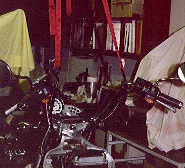
Rather than possibly damaging anything else, before loosening the handle bars, I threw a loop of rope through a rafter hook in the garage and tied them up. This way as the bars were loosened, they just kind of hung where they were supposed to be. After reading over the directions, I put more tie-downs on the back of the bike. This project wasn't going to be easy.
|
Hang 'em high, strapping up the handle bars. |
I needed to remove the tension on the front forks, so I put a small hydraulic jack under the engine. I only jacked up enough to note the forks had gone up a bit.
Next item to be removed was that round chrome cover over the stem bolt. The only thing that holds that cover on is the tension of the o-ring around its perimeter. To remove the cap, I removed the screw in the center, threaded in a long 6mm bolt (only a couple of threads) and pulled the cover up. The cover gave a little resistance but I didn't need to use any more than "finger tension." With the chrome cover out of the way, the stem bolt and head bearing were now visible.
I continued on to remove the four socket-head bolts holding the headlight in place (6mm hex key). Wrapped the headlight in a towel and layed it on the front fender (taking care that nothing got scratched). I then removed the four screws holding the instument cluster on (6mm hex key), wrapped it in a towel and set it on top of the headlight. After that, I removed both fork caps (17mm box or open end wrench). While holding the fork tubes from turning (with a 22mm open end wrench), I undid the fork tube retaining nuts (14mm socket). The only thing holding the yoke or fork bridge on at this point was the stem bolt. Removing the stem bolt was no easy task as it's big and it's tight. I used a 10mm hex key socket on a half inch drive breaker bar (mine is about three feet long). Once the bolt broke loose, I rechecked that the hydraulic jack was doing its job of taking the weight off the forks. I couldn't help but think to myself, if the bike isn't held well enough that when the stem bolt is removed, bike and forks will part ways and come crashing to the ground! Thankfully, no folly occured.
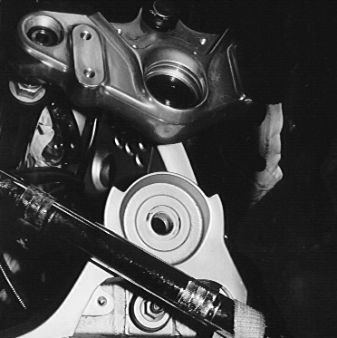 |
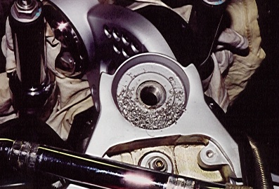
Fork bridge removed, the threaded hole in the frame becomes visible. |
This is where I was thankful that I had removed the fuel tank. After the stem bolt was undone, the yoke or fork bridge was lifted away. I didn't get very far before I realized the ignition wiring was way too short to carry the fork bridge to the press. The bolts BMW uses to attach the ignition to the fork bridge can't be undone, so instead of trying to drill the heads off the bolts, I opted to unplug the ignition. In order to unplug the ignition, the motronics unit had to be removed as well as the top of the junction box. The plug for the ignition is the big orange plug in the front, left hand side of the junction box. The plug has a little locking tab that needs to be depressed before it can be unplugged (that was the easy part). To remove the ignition wiring, the little clips under the steering head needed to be undone by poking about with a screwdriver. All the time I spent undoing these things I kept asking myself if I was going to be able to get it all back together. A footnote here: If I ever do a job like this again, I think I'll opt to drill out the ignition bolts!
My steering head bearing had been leaking so it needed replacing as well. Once I separated the fork bridge from the motorcycle, replacing the bearing and stem bolt was pretty easy. I removed the spring clip above the bearing and pressed both bearing and stem bolt out as a unit. I pressed the new stem bolt into the new bearing and that unit back into the fork bridge, finishing out by refitting the spring clip before I had a chance to misplace it.
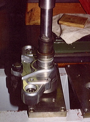 |
Pressing in the new bearing and stem bolt. |
Now comes the scary part, drilling and tapping the frame. With the words of the service guy echoing in my head, "If for some reason the hole gets drilled and/ or tapped wrong, the frame is junk!" I gingerly blundered forward. Looking at the tools BMW supplied, I was properly impressed, they have really tried to make it a job that can't be done wrong. Setting the drill fixture on the frame, it's obvious where it attaches. I threaded in the attaching bolts but left the fixture loose. Upon sliding in the locating mandrel, the fixture moved to its rightful position. I adjusted out any binding by the leveling screw, then tightened the fixture and checked again for any binding. With all aligned, I lubricated the drill bit and slipped it into the fixture. The actual drilling time takes all of about a minute (no turning back now). Next was fitting the tap guide, lubricating the tap and cutting the new threads. Tapping the threads was complicated by not having the proper sized tap wrench (some funny metric thing I guess). I found something in my scrap box that I soon modified to suit. With the threads cut and all the chips cleared out, I inserted the Helicoil (18mm x 1.5mm) and all was ready to go back together.
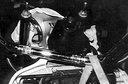 |
Fixture in place and tightened down, hard to see but it's there. |
 |
After drilling and tapping, the fixture is removed |
The only thing I had to remember upon assembly was fitting the new spacer that comes with the new stem bolt (it's a little longer than the stock one). The new stem bolt then needed to be torqued to 130Nm (that's Newton-meters, no, not Wayne Newton). In order to convert Nm to foot pounds (which all of my torque wrenches are in), the 130Nm needed to be multiplied by .738. So 130 x .738= 95.88, I figured 96 foot pounds was plenty close enough.
After the handle bars and instrument cluster was back on, I needed to get that ignition wire and plug back in. I'm here to tell you it is possible to get the wire and plug back in but man is it fussy. When everything was strapped down and tightened up, I loosely fit the headlight and turned the bars side to side to check for any binding or sticking. Snugged up the headlight, fit the tank and was back on the road before dinner time!
Copyright © 2009 Pokie Parmidge