by Pokie Parmidge 2013
A necessary job from time to time on my R1200c is a spline lube. Not exactly a fun job but a necessary one. If the line workers at the BMW factory did their job right, the drive splines on the input end of the transmission should have been lubed or greased. I repeat, should have. It seems a number of bikes left the factory with no lube at all on the drive splines. Sadly, this gives the drive splines a life of anywhere from about 8,000 miles to as much as 20,000 miles, not always depending on your riding style.
For the last several thousand miles, the thought of a possible break-down has worried away in the back of my mind. So, after re-settling my garage at our new house, it was time to take care of some pesky maintenence items. The big one, of course, a spline lube. For this job, I needed a block of time, a lot of space to work and a hook in the ceiling that can take a bit of weight.
I am fortunate to have a air lift bench to work on with tie-downs and a front wheel vise, as securing the bike for this job is VERY important. I rolled the bike up onto the bench and clamped the front wheel in the vise. For a little extra safety, I tied down the front forks to the bench. I discovered that it doesn't do a lot of good to use the BMW service stand to do this job as the place where it mounts will have to be taken off the bike before long.
|
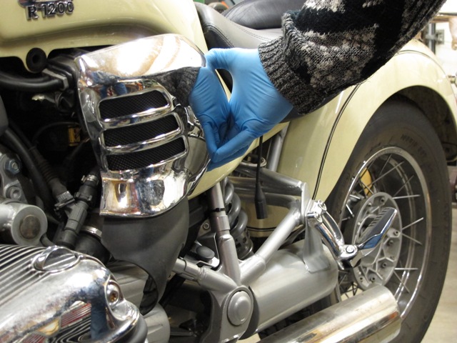
Now that the bike is secure, the tear down begins. I started off with pulling off the two chrome side covers. Tuck my fingers in behind and pulled off the bottom first, next the rear and finally the front. I had prepared a box with a soft rag in the bottom to lay the chrome panels so they wouldn't get scratched. |
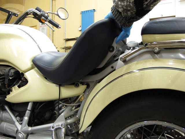 |
Next, the seat. Using a 4mm hex key, remove the 2 seat retaining screws (6mm x 35mm) and bushings. Lifting the seat at the back and wiggling it side to side while sliding the seat backwards. The seat isn't always easy to slide backwards as the rubber bumpers it sits on will often stick to the paint on the frame. |
 |
Using a 3mm hex key, remove the color panels under the seat on each side. The front of each panel uses a short screw with a single plastic washer (5mm x 12mm), while the rear uses a longer (5mm x 16mm) screw with a point, single steel washer and a steel bushing going through a rubber bushing in the color panel. The steel bushing is inserted from the back side so the large portion is against the frame. |
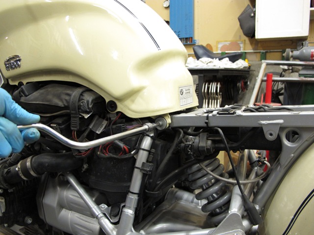 |
Ah yes, next thing off, the fuel tank. Using a 5mm hex key, remove the 2 bolts (6mm x 35mm) at the back of the fuel tank. Each bolt has one small washer, one large washer and one large rubber washer. Pinch off the two fuel hoses (on the right side of the fuel tank) using a hose pinchers, hemostats or pointy Vise Grips. If you choose to use Vise Grips, protect the rubber hose from the cerated edge of the grip jaws or gas will spew everywhere! Loosen the two hose clamps on the fuel lines and slide them up or down the fuel line to get them out of the way. Ease the rubber fuel hoses off the fuel lines and watch for any gas dribbling (I sometimes have to lube the lines with a drop of oil to get them to slip off). There will likely be a few dribbles of gas but it shouldn't be much. I will usually mark the top hose with a strip of masking tape just so I don't get mixed up when it comes time to put the tank back on.
Lift the gas tank at the back just enough to allow it to be wiggled backwards. I make sure I don't lift the tank too much because if the tank contacts the frame at the front, it will scratch the paint. Continue to wiggle the tank backwards until the front rubber bumpers free up. Lift the back of the tank just enough to slip in a small block of wood (2 inches or so). Pull the hose off the barb connecting it to the charcoal canister then pull the over-flow hose up and out of the frame and just let it dangle. Lastly, pinch together the top lockes of the fuel pump plug (on the right side just behind the fuel tank) and unplug it, again, just let it hang. Slide the tank back and lift it away. |
Undo and remove the battery, negative terminal first. Remove the tool kit. I'll also remove the battery strap and tool kit straps and put them somewhere they won't get lost. This would also be a good time to service the battery and charge if necessary.
 |
Remove the two circlips on the muffler mounts. Using a 15mm wrench or socket, loosen the two muffler clamps. I will then smear oil or silicone on the muffler mounting pins and by lifting the muffler up and down, the lubricant can be worked into the rubber hanger bushings. I also like to put a small scissor jack under the muffler as it's pretty heavy when it comes off.
NOTE: If a muffler is particularly resistant to sliding off it's header pipes, I will undo and remove the header pipes. I never beat on the muffler to get it off, I figure out what is hanging it up and deal with it (usually it's the headers). |
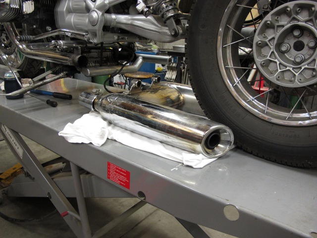 |
Unclip the wiring for the O2 sensor from the holding clips on the bottom of the transmission (the wire is long enough to just allow the muffler to set on the bench without having to remove the O2 sensor from the muffler). Lay a rag on the bench under the muffler and wiggle the muffler off it's mounts and set it on the rag. In this case I used an old "T" shirt. |
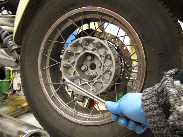 |
Using a 17mm socket on an extension and a breaker bar, break the rear wheel lug nuts loose. Don't take them out yet, just make sure they are loose.
Here is where I make sure the bike is heald securely. I tie down the bike at the front forks then place a scissor jack or the like under the motor, along with a piece of plywood on top of the jack (to reduce any chance of damaging the engine case and spread out the stress). As I'm lifting the bike, I keep going back and checking the tie-downs. If they start to get too tight, they'll need to be loosened a bit. If they start to get loose, then they'll need to be tightened. Jack the bike (under the engine) up just enough to be able to lift off the rear wheel. Undo the lug bolts and remove the rear wheel. |
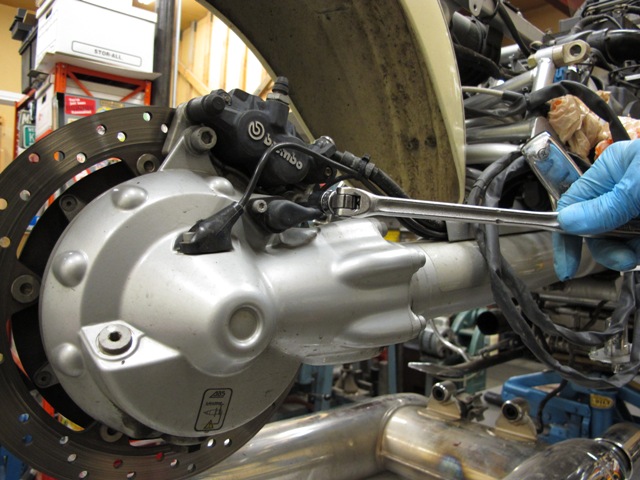 |
Withe an 8mm hex key, snap the bolts holding the rear caliper loose, undo and remove the bolts and lift away the caliper. Just let the caliper sit beside it's mount for now. |
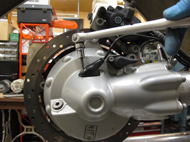 |
Using a 4mm hex key, remove the little bolt holding the speedo drive sensor and lift the sensor out of the case. It may give a bit of resistance as it also has a rubber o-ring that may stick to the case. Careful not to allow any dirt that may have collected around the base of the sensor to fall into the hole. I carefully waud up a bit of tissue and sitck it into the hole to reduce the chance of getting any dirt in it.
The tip on the speedo drive sensor is magnetic, check it to see if any bits of metal have been picked up by it. If the pieces of metal are just little bits of fuzz, wipe off the sensor and don't worry about it. If you find any "chunks" stuck to the sensor, this is indicating the rear drive is in need of attention. |
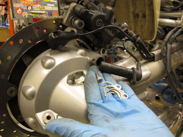 |
Clean around the ABS sensor, (if one is present). Using a T-25 Torx key, undo and remove the bolt retaining the ABS sensor. Under the sensor head, there may be some shims, while pulling out the sensor I remove the shims and put them together with the retaining bolt so they are not forgotten when things are going back together.
The sensor is quite long and may give a bit of resistance coming out as there is an o-ring in the case that may stick to it. After the sensor has been withdrawn, wipe it down and check for any damage on the end. When re-assembling, I usually put a smear of grease on the o-ring to assist with slipping the sensor back in. |
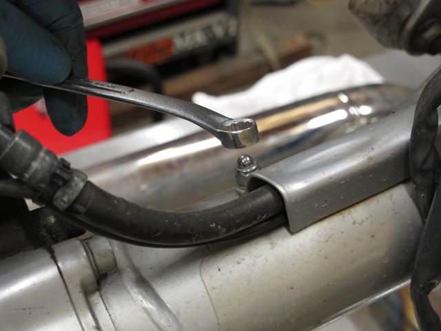 |
Next up is the channel for the hoses on the swing arm. Using a 10mm box-end, open-end wrench or socket, remove the two acorn nuts and washers holding the hose channel in place on the swing arm. Lift the rear caliper and sensors, along with the channel and just let the whole works dangle off the outside of the swing arm. |
 |
With a 6mm hex key, I'll next snap loose all the bolts holding the rear drive. Remove all six bolts. Once all the bolts have been removed, wiggle the rear drive side to side until it comes off. There are two hollow dowels holding the rear drive in place after the bolts have been removed, the wiggling side to side helps the rear drive come off those dowels. DON'T pry with screwdrivers! After the rear drive is off, set it down in an upright position so it doesn't leak oil all over. |
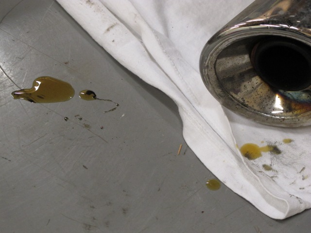 |
When the rear drive and swing arm are parted, a few drops of oil may come out. A few drops are ok, if more than about half a cup comes out there may be a seal problem. This is how much oil came out of my swing arm when it was parted, there is NO problem here. |
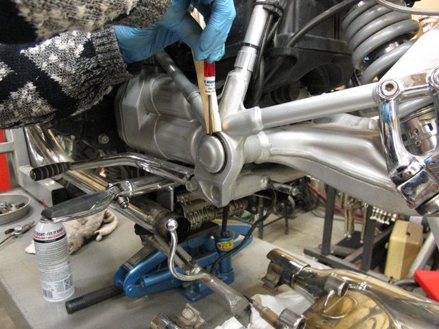 |
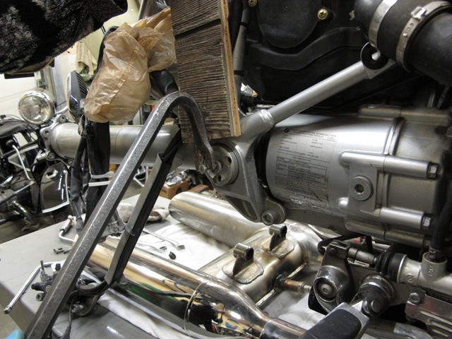
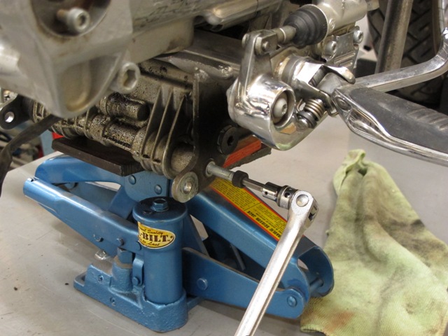
Next I'll go to the swing arm cap on the Left side of the frame. I'll spray a bit of silicone lubricant into the small space around the cap, all the way around (WD-40 would also work fine). The cap is held in place by an o-ring around the perimeter of the cap, by spraying silicone or the like in there, it helps the o-ring to slip out.
Using a small, flat blade screwdriver, carefully pry the cap off. I like to use a scrap of wood to stop damaging the paint on the frame. Pry a little on the top, then a little on the bottom until the cap finally comes off. Note the small hydraulic scissor jack under the engine. |
 |
I like to undo the rear shock mounts now. Using a 14mm wrench on the head of the bolt and a 15mm wrench on the nut of the lower mount, undo the bolt and nut but don't remove them. Go to the top mount of the shock and do the same. With the bolts loose, the shock will be easy to remove but will also support the swing arm while the swing arm mounts are undone. |
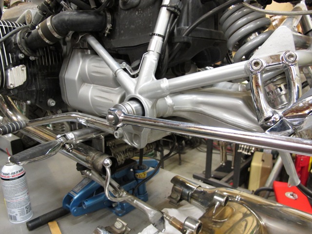 |
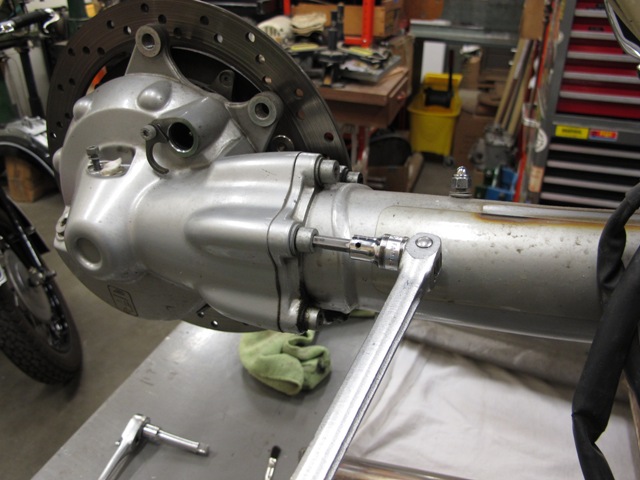
With a 30mm socket and long breaker bar, break the lock nut loose. The nut doesn't have to be removed, just loosened. |
 |
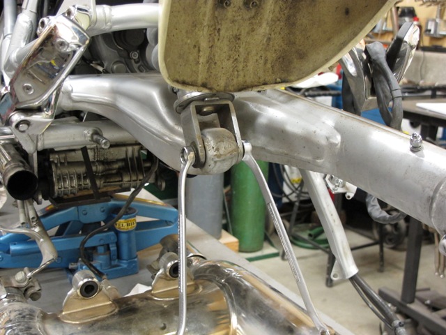
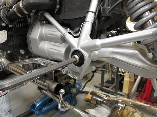
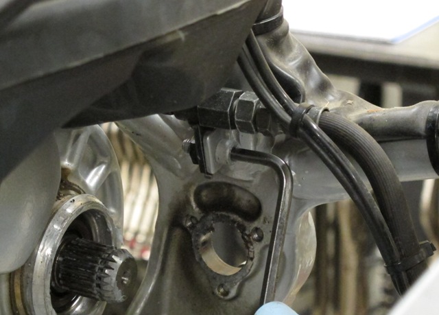
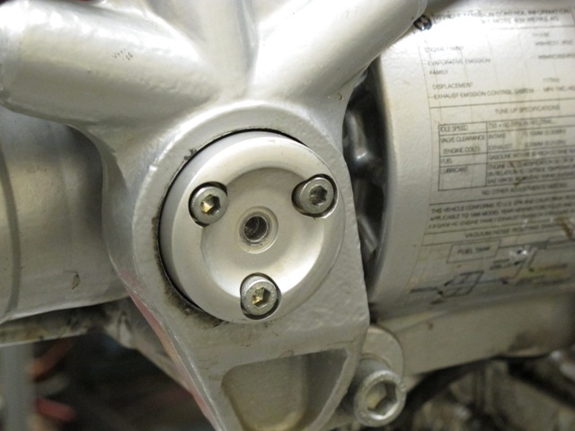
On the right hand side of the bike, the swing arm pivot needs to be dealt with. Using a 5mm hex key, remove the three bolts around the perimeter of the plug as well as the one in the middle. The three bolts around the perimeter hold the pivot in place while the one in the middle is simply there to help pull the pivot. |
 |
Out of my collection of old 6mm bolts, I'll replace the center bolt with a longer one, asy about an inch and a half long. I also like to keep a few scraps of wood around to press against things so as not to damage the paint. While holding a piece of scrap wood (in this case, plywood) against the frame and using a pry bar, pull out the swing arm pivot. I usually find that the pivot won't come straight out, instead, I will have to pull a bit on the top then pull a bit on the bottom. Sort of "rocking" it until it comes out. |
 |
Using a 12mm hex key, back out the swing arm pivot on the left side of the frame. When the pivot un-threads to the end, it will still be stuck in the bearing. I just wiggle the swing arm back and forth until the pivot comes out.
While holding the swing arm up, remove the lower shock bolt. Now that the swing arm is free, the shaft rubber bellows will have to be worked over the shaft to remove the swing arm. I find that if the swing arm is tipped down on the left, it usually slides out without too much problem. |
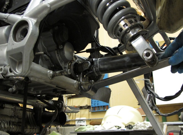 |
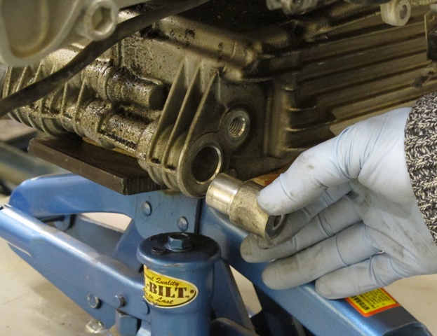
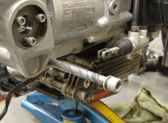
To remove the shaft from the back of the transmission, I'll put a strip of duct tape on the frame member just below the shaft and using a ply bar (or in this case a "Super Bar"), pop the shaft off the transmission drive splines. The shaft is heald onto the transmission drive splines by a cir-clip that will just expand and contract with a bit of pressure. Strong enough to hold the shaft in place while running down the road yet weak enough to come apart when needed.
I always have to resist the temptation of prying against the back of the transmission flange. It's only aluminum, if that gets broken, it will be very expensive. Now that the swing arm and shaft are out, remove the upper mounting bolt and nut from the top of the rear shock and remove the shock. |
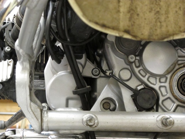 |
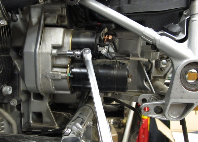
With the swing arm and shock out, the next step is real easy. Using a 5mm hex key, remove the bolt in the back of the starter motor cover. Once the bolt is out, the cover can be moved back, lowered down, rotated so the top of the cover is clear of the frame, hold the shift lever down and the cover will lift out. |
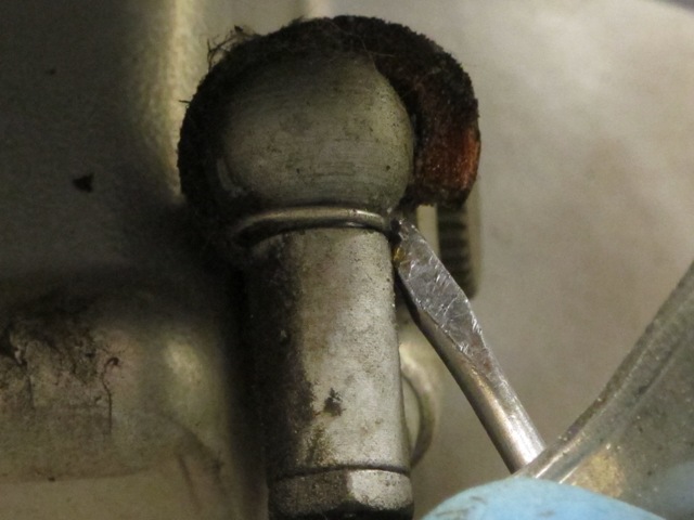 |
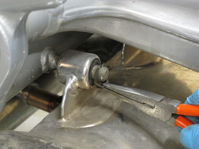
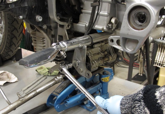
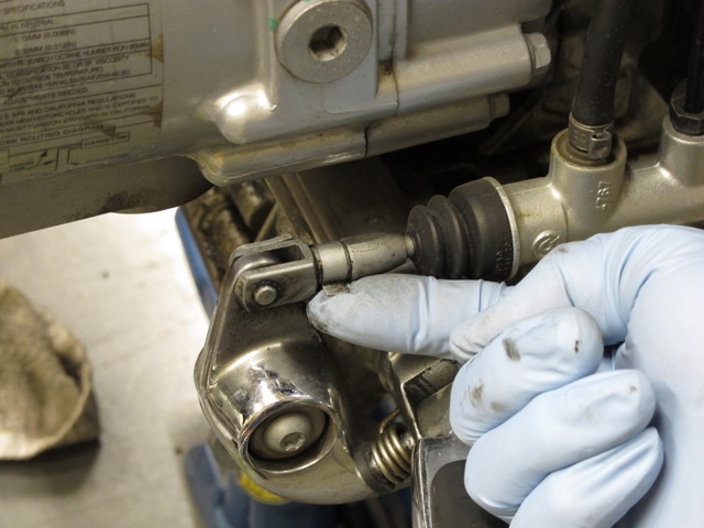
These next few photos show how I get the shifting linkage retaining clip out.
Using a flat blade screwdriver,...... |
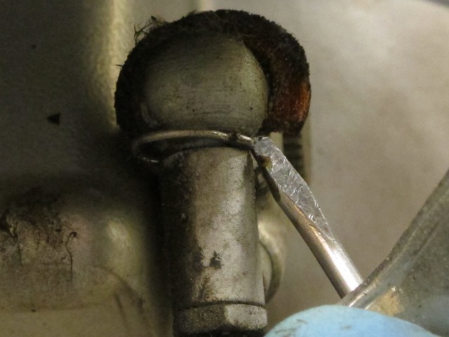 |
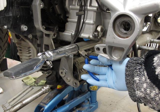
..... push the loop of the clip back,...... |
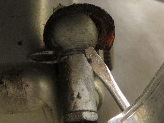 |
..... until it clears the body of the linkage. Once the clip is clear of the linkage body, it can be slid out. With the clip out or removed, using that same screwdriver, pry the socket off the ball of the transmission shift lever. This, ladies and gentelmen is the area where all the dirt collects and makes the bike hard to shift. Clean and lube this often. You will also note here, the lubrication dougnut on my bike is broken. This will be replaced on re-assembly as it not only helps keep the linkage lubricated but also helps keep the dirt out. |
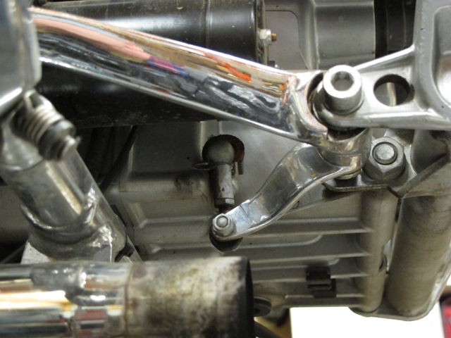 |
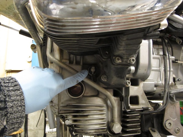
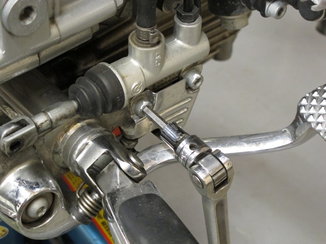
Here is a little further back view to show where the shift linkage is in relationship to the foot shift lever. |
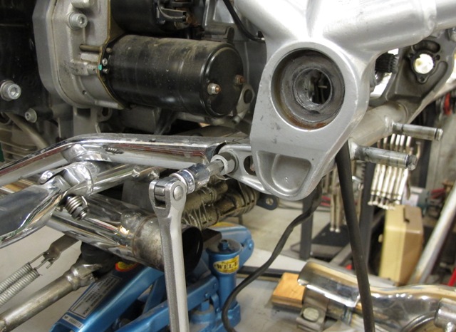 |
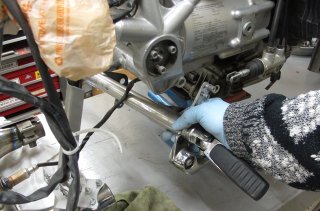
The shift lever pivot will require an 8mm hex key to undo. If it hasn't been lubricated in some time it may also require the nut in behind to be held with a 19mm wrench. The space here is very tight, a thin wrench may be needed. Once the bolt is removed, the shifter and it's linkage can be lifted out. |
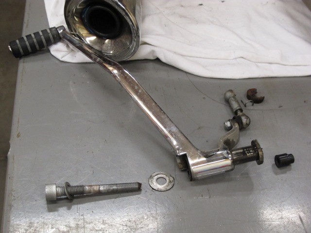 |
Here is a photo showing all the shifter parts as removed. The pivot bolt has a shaft with a long, rounded nose that rides in a plastic bushing as seen on the right. The large flat washer, seen just to the right of the pivot bolt, goes between the frame and the shifter. |
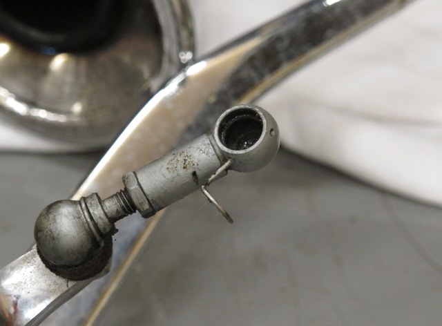 |
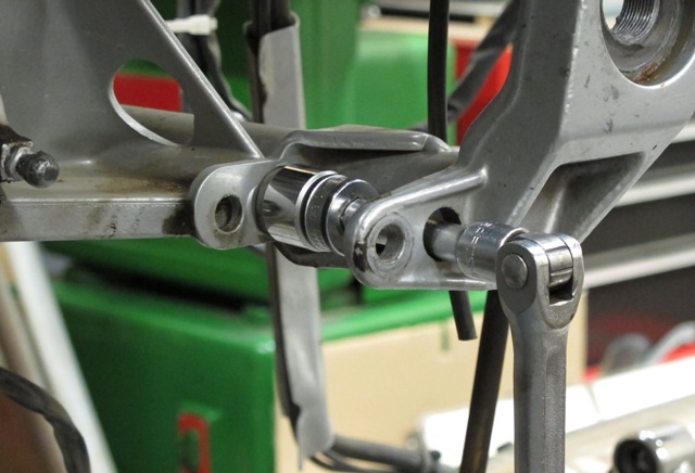
Just for a bit of clearification, here's a close-up of the shift linkage socket and retaining clip and how it fits together. The clip slides all the way up and into the second hole before it is snapped closed over the body of the socket. Getting the clip all the way through the second hole may take a few tries. |
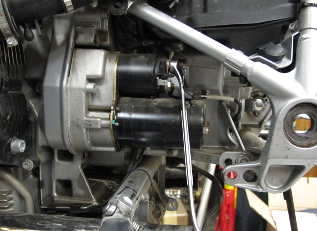 |
Ok, enough on the shifter, let's get the starter out.
First off, pull off the black wire terminal and just let it hang. The battery had better be out or at least disconnected by now! Next, take a 13mm box end wrench and undo the positive terminal on the starter and remove the positive wire (red wire with a black plastic cover). Re-fit the nut and washer to the starter so it doesn't get lost. |
 |
Using a 6mm hex key, remove the two bolts holding the starter in. One bolt is obvious, the other is on the lower back of the starter. Lift the starter out. |
I don't usually have any trouble getting my muffler off, so at this point my header pipes are still on. Well, now I need to take them off as well. Using a 13mm socket, extension and ratchet, undo the four nuts holding the header in place, (two on each side). Lift the headers off and set them somewhere safe. I usually just put the washers and nuts back on the studs so as not to misplace them. When reassembling them, I'll always use anti-seize on the exhaust nuts and studs.
 |
With an 8mm hex key, loosen and remove the big counter-sunk bolts holding the foot peg mount on. One on each side. |
 |
I won't be able to get the foot peg mount off unless I cut the cable tie holding the wires to it. So, out comes the side cutters and start cutting. While I've got them out, there is another couple of ties that need to be cut. The strap holding the clutch bleeder to the frame, (don't lose the rubber piece that it uses to space it away from the frame) and the strap holding the bundle of wires at the starter motor. |
 |
Follow the oil pressure wire, on the right side of the motor. Unclip the wire from it's clips along it's route then unhook the terminal itself. This is just a spade terminal and will easily slip off. Just let the wire hang. |
 |
With a 6mm hex key, loosen the long bolt on the lower right of the foot peg mount but don't remove it quite yet. |
 |
Unhook the rear brake linkage pin by flicking it up with a finger and slipping it out to the rear. |
 |
Using a 5mm hex key, remove both bolts (6mm x 16mm) holding the rear brake master cylinder in place. The little chrome cover will come off as well. Just let the master cylinder sit where it wants, it will be bolted back up before long. |
With a 4mm hex key, remove the bolt (5mm x 8mm) holding the brake switch in place, just let it dangle by it's wire.
It's now time to take off the last remaining bolts for the foot pegs. Using a T40 Torx key, remove the last two remaining bolts holding the foot peg bar on. Withdraw the long bolt (8mm x 195mm), loosened but left in to hold things while other jobs were done.
 |
The foot peg bar or mount may now be lifted away. |
 |
On the right hand side, when lifting away the foot peg mounting bar, note the bushing. It's easy to knock this bushing off. After removing the foot peg bar, I'll just make sure the bushing is poked back in it's hole. |
 |
Using a 5mm hex key, remove the bolt (6mm x 16mm) holding the rear brake line to the frame. On the right hand side of the frame, just above the swing arm pivot. This bolt NEEDS to be removed so as not to damage the brake line. Once the bolt has been removed, just allow the brake line to hang. |
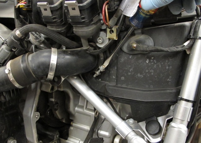 |
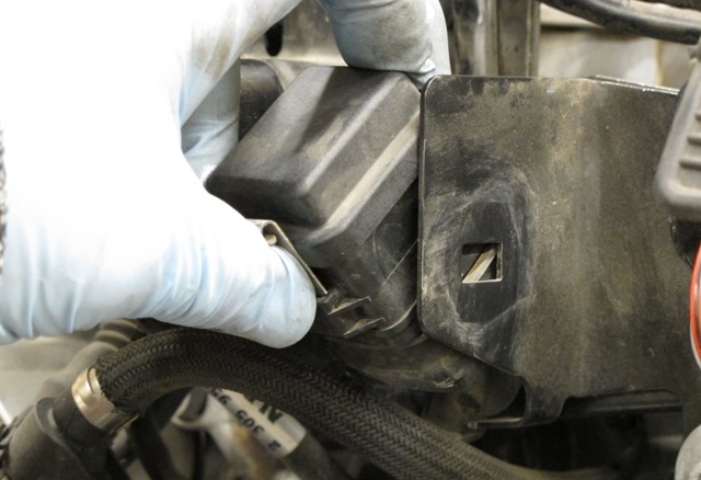
With a flat or spade screwdriver, loosen the hose clamps on the intake tubes. Push the intake tube down (towards the head) and pivot the top of the tube out of the air box. I will usually use a squirt of silicone or a drop of oil (forced between the tube and the rubber) to aid in slipping the tubes out. After the tubes have been removed, stuff a rag or paper towel into the open injector body so nothing falls in. |
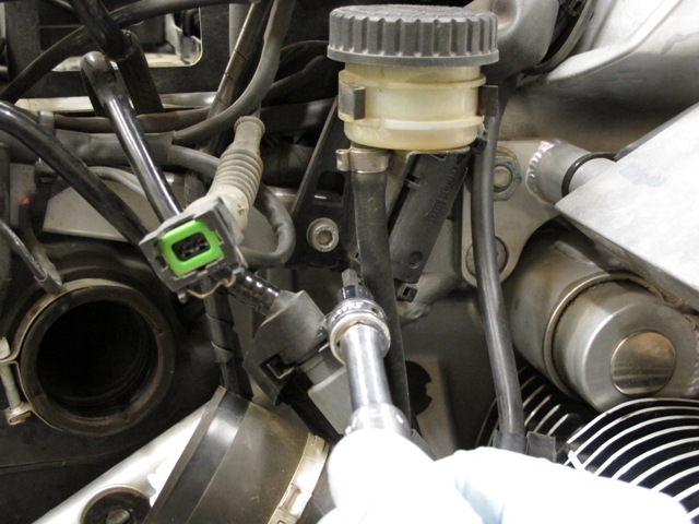 |
Press in the clip on the right hand injector plug and wiggle the plug off. Watch the green plug gasket doesn't get lost, I always check it and press it back into the plug should it become dislodged.
Using a 5mm hex key, undo and remove the bolt (6mm x 16mm) holding the rear brake reservoir to the frame. Leave the reservoir right where it is. If necessary, wrap a rag around it to keep it upright. |
Ok, so I forgot to take a photo of this next step, you will just have to use your imagination. On the back of the air box, there is a hose that has a dog-leg or double bend (a "Z" shape) in it. This hose needs to be pulled off it's hose barb and just left where it is. This hose goes to the electric switch before the carbon canister. At this time it would be convenient to pull the other hose from the carbon canister out of the loop on the bottom back of the air box.
 |
Back on the left side of the bike, rotate the fuse box down and remove it from it's mount. There may be two fuse boxes, remove them both. Just let them hang. |
 |
Again, a 5mm hex key, loosen and remove all three bolts holding the fuse box mount to the frame. Keep track of all the washers and spacer and make sure they get back in the right order.
This order is,..... Lower rear bolt, 6mm x 25mm, large washer and small wavy washer. Upper rear bolt, 6mm x 16mm, large washer and a spacer 12mm dia. x 2mm thick. The spacer goes in the hole of the fuse box mount, against the frame. Upper front bolt, 6mm x 16mm, large flat washer. |
No picture here as this next step is a service item. Pinch together the clip of the plug on top of the air box and remove the plug. Using a philips screwdriver, undo all four screws on the top of the air box (the screws don't have to come all the way out, only enough to free the top of the air box). Remove the top of the air box and remove the air filter. This would be a good time to replace the air filter element if it looks cruddy. This would also be a good time to vacuum out the air filter chamber. If your bike has spent the winter all alone under cover or in an area frequented by mice, you may find a mouse nest in here. Next time you park your bike for a long period, stuff a rag in the air intake snorkel to keep those pesky mice out of there.
 |
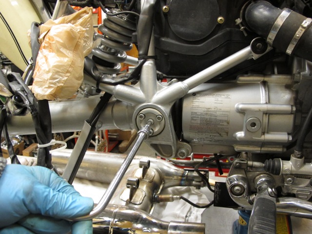
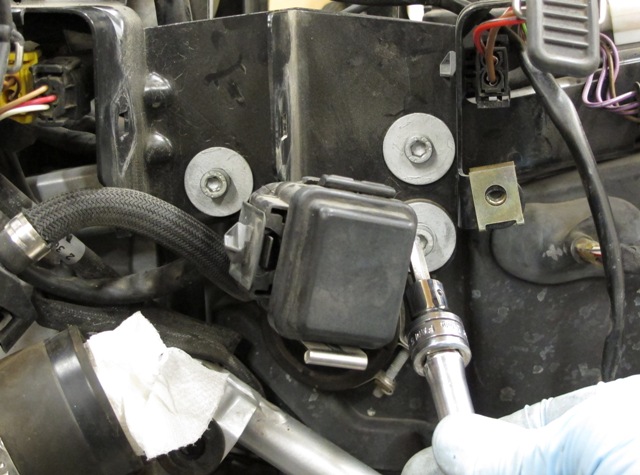
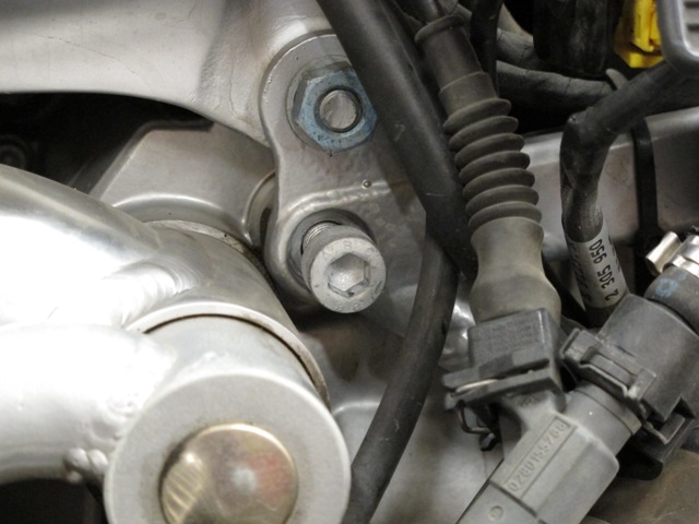
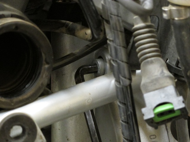
To remove the lower, rear transmission mounting bolt, I start off by spraying the visable part of the bolt, in the middle of the lower, back of the transmission case with something like WD-40 or penitrating oil.
The nut on the lower, rear transmission mounting bolt takes an 18mm socket, with a 3 inch long extension through the hole in the frame and a breaker bar. |
 |
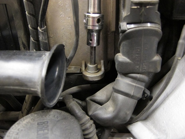
Using a 10mm hex key on the other end of the mounting bolt, undo and remove the nut. I like to turn the bolt after the nut has been removed to spread around the lubricant that I had sprayed in earlier. Withdraw the bolt (12mm x 235mm). |
 |
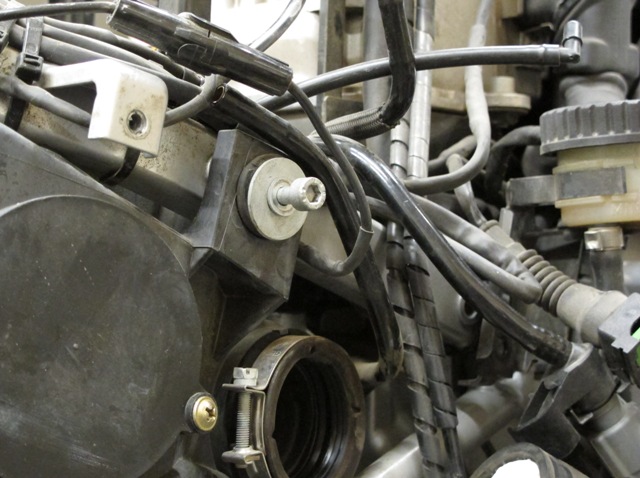
Using an 8mm hex key, remove the two (one on each side of the bike) lower, front frame mounting bolts (10mm x 45mm), just behind the front swing arm.
Using a 16mm socket, loosen (yes, only loosen, don't remove) the nuts above the bolts that were just removed. |
 |
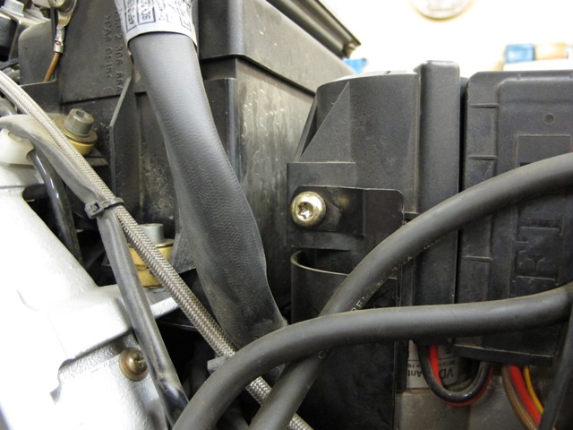
With a 5mm hex key, remove the bolt (5mm x 35mm), with a large washer and a small wavy washer holding the air box to the frame on the right hand side of the bike. There is an aluminum spacer (14mm OD, 6.5mm ID, 8mm thick) on the inside of this mount, don't lose it, it will need to be put back when reassembling. |
No photo again!
Using a 10mm socket, remove the two nuts and wavy washers in the base of the battery box. It would probably be a good idea to vacuum this out, all kinds of dirt and dead bugs collect in here.
 |
With a 5mm hex key, remove the two bolts holding down the ABS unit (if the bike has ABS). The ABS unit will take care of itself when the rear frame is lifted. |
 |
Using a T30 Torx key, remove the last bolt holding the ABS unit, it's on the left hand side of the bike. Again, the ABS unit will take care of itself when the rear frame is lifted. |
 |
One more item to take off before attempting to lift the rear frame. Using a T25 Torx key, remove the screw on the right hand injector and wiggle the injector out of the injector body. At this point I'll wipe the injector o-ring and look for any cracks or splits in the o-ring. After wiring it down, I usually just lay it up on the frame so it's out of the way.
Using a spade or flat blade screwdriver, loosen the clamps (62mm diameter) on the injector tube and wiggle it off. I like to spray a little silicone or WD-40 on to the rubber sleeve/ intake tube to allow it to slip a little easier. |
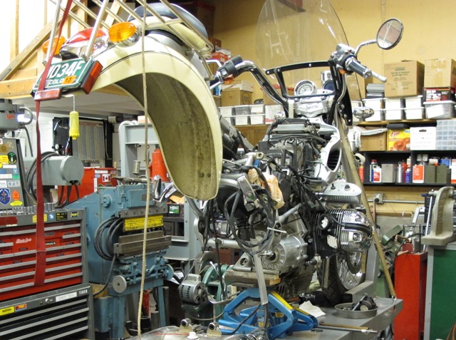 |
This is where that hook in the ceiling comes in real handy. I'll lift the rear frame a bit, check for any tight wires or hoses. Lift it a bit more, check again. I'll keep lifting and checking until I feel I have enough room to get all the transmission mounting bolts out. I like to use those big red motorcycle tie downs folks use to tie bikes down to a trailer.
This photo shows the frame up high enough to remove the transmission mounting bolts. The air box is pushed against the battery box, pressing it up and against the ABS unit. The ABS unit also is pushed up and forward to get enough room. No, the ABS unit does not have to be removed. Yes, it's tight but nothing has been over-stressed. Sorry there's so much stuff in the photo, it kind of makes it hard to see the bike. I have a very full garage. |
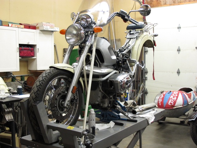 |
Here's a view from the front with the rear frame lifted. |
 |
With the rear frame lifted, there's just enough room to get the top mounting bolts undone and removed. Using a 6mm hex key and an extension, the top bolts (8mm x 55mm) can be loosened and removed. |
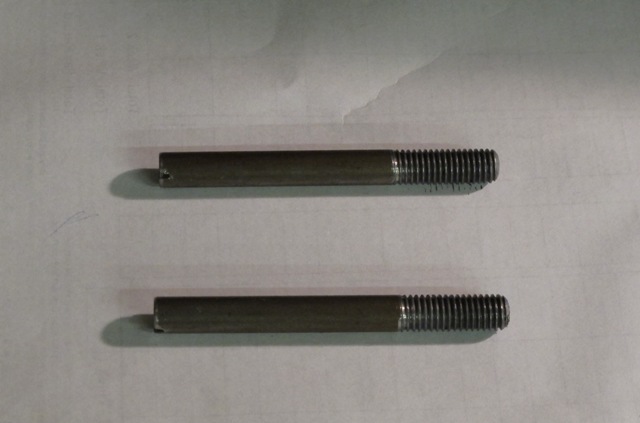 |
Here is a couple of tools I needed to make. I made them out of a piece of 5/16 diameter or .312 diameter rod but they also could be made from a couple of long 8mm bolts, just by cutting the heads off. Come to think of it, the heads don't really need to be cut off if the bolts are long enough. These are 3 inches long with a thread length of one inch. |
 |
Remove the two middle transmission mounting bolts (8mm x 76mm) and replace them with the two "modified" bolts. I like to coat these with some anti seize to make them easy to get in and out.
With these modified bolts in place, once all the transmission mounting bolts have been removed, the transmission can be slid back and forth and still be supported. Using that same 6mm hex key and extension, remove the two bottom transmission mounting bolts. |
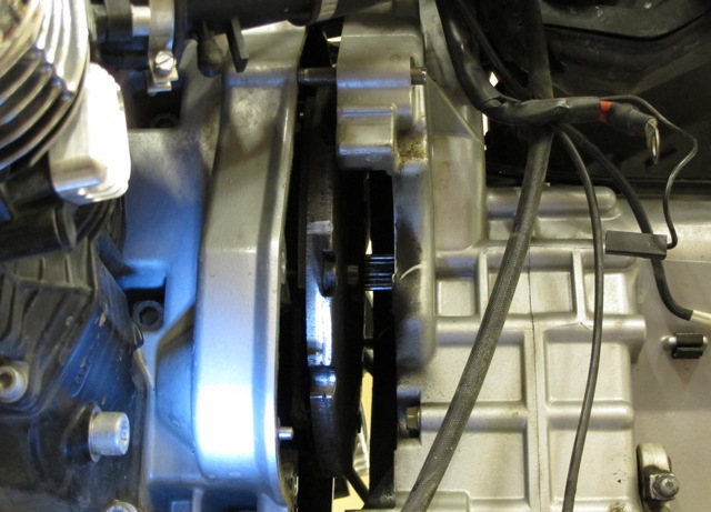 |
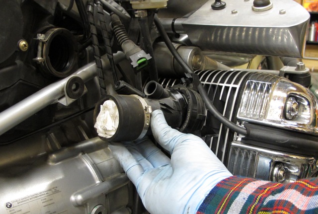
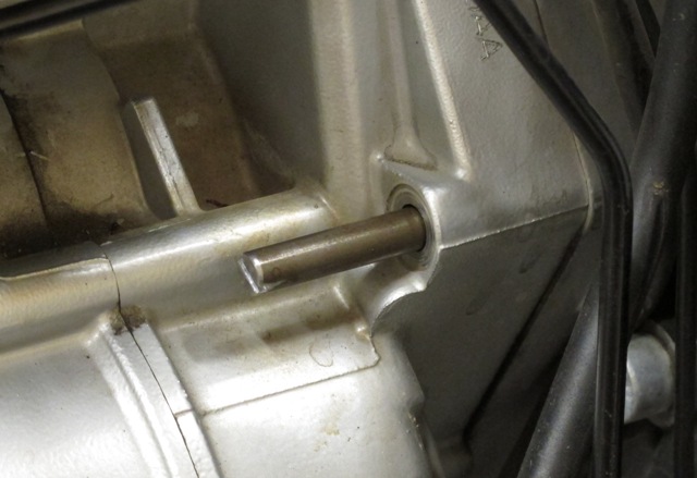
There is now enough room to clean and inspect the transmission drive splines. Just have to wiggle the transmission back and the splines will be exposed. When ever I use a cleaner in this sort of area, I always make sure to use a cleaner that will evaporate very quickly, like lacquer thinner or brake cleaner, something that will evaporate quickly and not leave any film behind. |
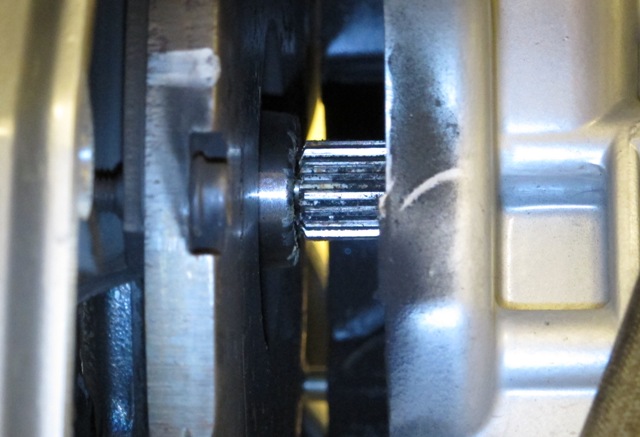 |
The splines on my transmission are in good shape, now to clean all the way around and lube all the way around. Each and every spline needs to be cleaned and greased, yup, every one. All there needs to be is a film of grease, if gobs get put in there, it will end up on the clutch plates,...... not a good thing.
I like to grease the splines, push the transmission back on then slide it back and do it again. I will repeat this about three times or until I feel all the splines on both the transmission and the clutch plate has a coat of grease. |
After I was happy with the way the splines were lubed, time to start going back together. Push the transmission back into place. Thread in the two top transmission mounting bolts, after, of course, applying anti seize to the threads. Thread the bolts home but don't tighten them yet. Remove the two home-made studs and thread in the remaining four transmission mounting bolts, after applying anti seize to their threads. When all six mounting bolts are in, tighten in a cross fashion, so everything is nice and even. The torque spec for the bolts that hold the transmission to the engine case is 16 foot pounds. This Torque is just for reference, it is possible to get a torque wrench on the lower bolts but good luck getting a torque wrench on the upper bolts.
Once the mounting bolts for the transmission are tight, the rear frame can be lowered back to it's normal position. While the frame is being lowered, watch for any wires or tubes that may get pinched. Also, this is a good time to watch the clutch bleeder tube ends up in the proper location or the frame may have to be lifted and it's location corrected.
Smear grease on the long lower bolt for the transmission lower mount and slide it in. Thread the nut on but don't tighten it yet.Apply anti-seize to the two upper, front sub frame bolts and thread them in. With all the sub frame mounting bolts in, tighten the mounts. Torque for the rear frame to the engine case is 30 foot pounds. The torque for the long bolt or frame to transmission is 52 foot pounds.
Thread in all three screws that hold the ABS unit in place. When all three screws have been threaded in, tighten the screws.
Thread on the two nuts and wavy washers to the base of the battery box and tighten.
|
Thread in the two bolts and large washers that hold the fuse box mount and tool tray in place. Don't forget the washer that spaces the rear mount. Thread in the bolt and large flat washer for the air box at the same location. Tighten the mounting bolts. |
|
Fit the long bolt with the large flat washer and wavy washer to the other side of the air box, remember that aluminum spacer? It goes between the air box mount and the frame. I hold the bushing with needle nose plyers and insert it from the top, slide the bolt through then tighten. |
Thread in the bolt for the rear brake reservoir and tighten it.
Refit the fuse box (one or two depending if you have other accessories) by poking into the square hole in the mount and rotating the box up.
Push the "Z" shaped tube from the charcoal canister back onto the hose barb on the back of the air box.
Tuck the wire for the neutral switch back into it's clip on the side of the transmission case.
Reattach the wire and clip for the oil pressure switch and tuck the wire back into it's clips as well as the wire for the side stand switch.
|
Mount and tighten the electric start motor (15 foot pounds). Don't forget to hook up the wires and tighten the positive cable terminal (7 foot pounds). |
Refit the air filter element, top and screw down all four screws holding the top in place. Refit the sensor plug on top of the air box cover.
Lube and refit the shifter and shifter linkage.
Fit the starter motor cover, make sure the two pins on the front of the cover are in their proper holes. It's completely possible to mount this cover ascue. Don't forget the 6mm bolt in the back. This would be a good time to run the hoses from the charcoal canister and the battery breather tube through the rubber loop on the back of the starter motor cover.
Fit the rear brake hose and mount above the right swing arm pivot.
Time to refit the rider foot peg mounting bar. Remember the two spacer bushings on the right side. The long bolt on my bike was rusted, so before I started the bolt back in, I coated the threads with anti-seize and the bolt itself with grease. I make sure all the mounting bolts are at least started before tightening anything.
When fitting the rear brake switch, first align the one hole with the bump on the mounting plate, then align the second hole with the threaded hole. Thread in the bolt and tighten it. Slide the pedal into the brake linkage and fit the pin (smear grease onto the pin) and clip it down. Put both bolts into the chrome cover and slip the works into the holes in the master cylinder. Thread in the two bolts and tighten. Resist the temptation of pumping the brakes as the rear disk isn't on yet.
Fit the hose clamp to the right injector tube, smear the end of the tube with a drop of dish soap (to help it slide in) and slip it into the tube on the head. Smear a touch of dish soap to both ends of the right intake tube (again to help it slide). Push the intake tube into the injector tube, pivot it and slip it into the rubber tube in the air box. Tighten all the right hand hose clamps. Smear a touch (it doesn't take much at all) of dish soap on the o-ring of the right injector and slip it into it's mount on the injector tube. Hold it steady while threading in it's screw. Tighten the screw but don't go crazy, the screw is going into plastic and if tightened too much, may strip. Plug in the injector plug, an audible click should be heard.
Over to the left side of the bike. Same proceedure, lube both ends of the intake tube with a touch of dish soap. Slip into the injector tube first, then into the air box. When happy with it's location, tighten the hose clamps.
This is a good time to strap the clutch bleeder tube to the frame down tube.
While there's still lots of room, grease the upper rear shock bolt and hang the rear shock. Thread on the nut but don't tighten it. The shock will need to be loose to be able to move the shock around to mount the swing arm.
Lube the splines on the universal end of the drive shaft. Slip the splines onto the output splines of the transmission. Hold the drive shaft level and "rap" the end of the shaft with a rubber hammer to drive the shaft retaining clip onto the transmission shaft. The retaining clip is inside the splines of the drive shaft. Check that the drive shaft is now firnly heald to the transmission output shaft.
Grease the lower shock bolt and set it down on the left side of the bike. Smear a touch of dish soap on the on the inside, transmission end of the drive shaft rubber bellows (to help it slip onto the transmission output flange). Also smear a touch of dish soap on the lip of the output flange of the transmission.
Slide the swing arm over the drive shaft. While lifting the rear shock, slide the swing arm all the way on. With a bit of wiggling, the drive shaft boot will slide over the universal joint and onto the transmission output flange. Slide in the lower shock mounting bolt to hold everything in position while lining up the swing arm pivots.
|
I like to start with the swing arm pivot on the left side of the bike. After greasing the left swing arm pivot bolt, visually line up the hole in the frame with that of the swing arm and start the pivot into the hole. Thread the pivot in two or three threads. |
 |
The swing arm pivot on the right hand side of the bike is a little more involved.
Grease the right hand swing arm pivot (to aid sliding it in). Using three long 6mm bolts, line up the pivot holes and press the pivot in as far as you can by hand (it won't be far). Fit these longer bolts to the three holes (I use 3- 6mm socket head cap screws with a pitch of 1.00 mm x 25mm long) slowly and evenly, pull the pivot into the frame and pivot bearing. These longer bolts will bottom out when the pivot is only about half way in. Remove the longer bolts and thread in the bolts that originally came out. Again, slowly and evenly tighten the bolts and pull the pivot the rest of the way in. Tighten the bolts, torque these three bolts to 7 foot pounds. Fit the middle bolt and tighten. |
Thread in the left hand swing arm pivot and tighten to 5 foot pounds, don't over tighten this pivot as it is the bearing pre-load. Tighten the large lock nut, BMW calls out for a torque of 118 foot pounds for the lock nut.
Grease the splines on the short section of drive shaft and get at least one rear drive mounting bolt ready to be threaded in. Press down on the gear shift lever and put the transmission into first gear. If the transmission won't go into first gear, try second. If it still won't go into gear, rotate the output shaft back and forth until it goes into gear, DON'T force it.
Look up the hole in the swing arm and note the position of the drive shaft (likely it will be just laying on the bottom of the swing arm tube). Tip the drive shaft on the rear drive just before the universal joint to mimic the position of the drive shaft in the swing arm. Slip the rear drive on while "rocking" the brake disk until the two shafts line up and slide together or couple up. While holding the rear drive in position, thread in that one mounting bolt. Because the transmission is in gear (see previous paragraph), if the rear drive is correctly mounted, the disk won't turn very far without locking. If the disk can be turned around and around, the two splined shafts of the drive shaft and the rear drive have not coupled (not connected) and the rear drive will have to come off and the proceedure will have to be done again. It's not unusual for me to have to do this a few times before the two shafts couple up properly. Once the rear drive has coupled, the rest of the mounting bolts can be threaded in and the rear drive pulled up. The torque for the rear drive mounting bolts is 15 foot pounds.
This is now a good time to tighten the mounting bolts for the rear shock, both top and bottom. BMW suggests the torque on these bolts be 37 foot pounds.
Lift the rear brake caliper and set it back in position on the rear disk. Thread in the two bolts and tighten. Suggested torque on the rear caliper bolts is 30 foot pounds.
Wiggle the hose cover back into position on the swing arm, thread on the two chrome acorn nuts and wavy washers. Snug down the nuts. Because these nuts don't come off very often, I like to apply anti-seize to the threads of the studs. Don't over tighten these nuts as the studs will break off and there's no good way to stick them back on without removing the swing arm again.
|
Smear a little grease on the shaft of the ABS sensor to help it slide in past the o-ring in the rear drive case. Slide the ABS sensor in. Before threading in the mounting screw, refit the shims that came off when the ABS sensor was taken out. If the shims have been misplaced, the ABS sensor will have to be checked for location with a feeler guage and new shims procured. Thread in the mounting bolt and tighten to 3 foot pounds (not much more than finger tight). |
Clean the speedo pick-up, put a smear of grease on the o-ring and slip into it's hole. Thread in the mounting bolt and tighten to about 3 foot pounds.
Smear a touch of grease to the two pins on the frame that the muffler mounts on. Lift the muffler and slide onto the pins and slip on both circlips. With the muffler held in place, tuck the O2 sensor wire back into it's clips on the bottom of the transmission.
Apply anti-seize to the threads of the studs for the header pipes on the heads. Apply anti-seize to the area of the header pipes that slip into the muffler. Fit both header pipes along with their nuts and washers. The muffler and header pipes will go together easier if you fit the muffler first then the headers.
NOTE: There have been times I've had trouble mounting the muffler because the back end of the muffler hits the swing arm rear drive flange. I get around this by mounting the rear wheel and letting the bike down onto it's wheels. It may even require the suspension be compressed a bit.
While the muffler clamps are still loose, this would be a good time to remove the nuts from the clamp studs and coat the threads with anti-seize before putting them back. Thread the clamp nuts back on with the washers and such, position the clamps and tighten.
If it hasn't been done yet, fit the rear wheel and tighten the lug bolts. The tightening of the lug bolts needs to be done after the bike's weight is back on it's wheels. Initial tightening is to 37 foot pounds (using a cross pattern). Final tightening is to 77 foot pounds. This final tightening should be re-checked after test riding.
Fit the tool pouch and strap it in.
Slip the battery back in. Watch which direction the battery terminals are set, don't hook it up backwards! Red is positive, black is negative. Hook up the battery terminals and tighten them down. Fit the retension strap over the top of the battery.
Fit the gas tank, fit the color panels, fit the chrome side covers (don't forget to check the rubber doughnuts holding the covers on), fit the seat and it's done!
Because the battery has been out, the throttle position sensor may need to be reset. Turn on the ignition (don't start the bike), roll the throttle tube slowly from idle position to full throttle position three times, turn off the ignition. The bike should now be ready to start and ride.
Wow, now that was a big job!
For this article, I didn't pull my transmission all the way out. I didn't pull the clutch slave or the neutral switch, they had enough room to stay attached. Judging by how much room there was to push the transmission back and lube the splines, I think there would also be enough room to get the transmission out. I haven't tried it but I do think it could be done. With everything being so close, I don't think I would attempt removing the transmission without an extra set of hands.
Copyright © 2013 Pokie Parmidge