 |
Wiggling the cap off, wiggle, wiggle, wiggle. |
(Altering the Cruiser Tick)
Pokie, Feb. 2000
This job, as with any job, I consider safety of both bike and body. If working on the bike on the side stand, strap the stand to something solid, (I usually strap it to the front wheel). This way, the bike can’t roll and the stand won’t fold up unexpectedly. Another thing to consider is the bike “high siding” while you are working on the low side. Set a stool, box or block of wood under the high side cylinder head to stop the bike from falling over. With safety considerations out of the way… let’s get started.
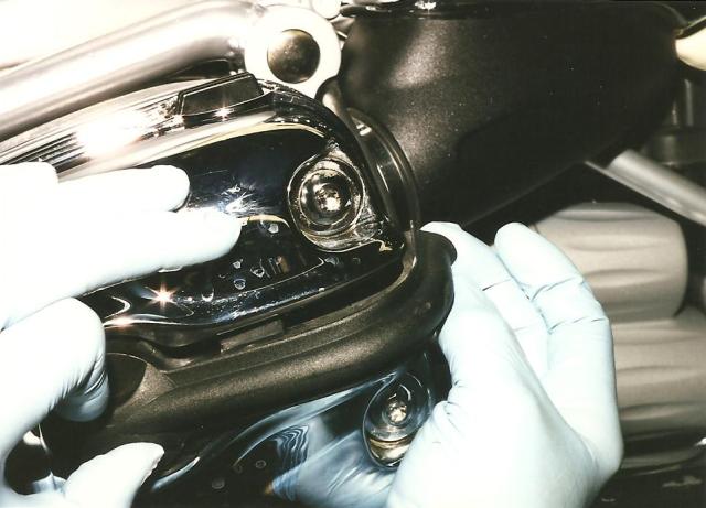
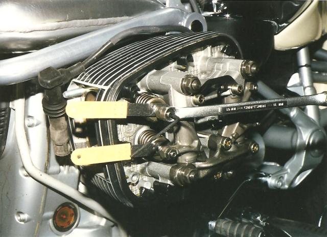
Remove the plastic trim strip on the valve covers, this trim strip covers up the H/T lead and sparkplug cap. It’s tempting to reach for your pliers, but don’t do it. The covers will “pop” off using just your fingers. Pinch the middle of the cap with one hand whilst hooking the edge with your other hands index finger, now wiggle the cap until it comes off.
|
Wiggling the cap off, wiggle, wiggle, wiggle. |
To pull off the sparkplug cap; there is a little black plastic tool in your tool kit for this job but if you don't have one in there, it’s possible to do it with a pair of pliers (but I really don’t suggest it). Instead, may I suggest buying the BMW special tool. Special tool #12 3 520 is plastic and it’s pretty cheap. Hook the tool under the top of the plug cap (opposite the H/T lead) and pull straight out using a kind of jerking motion.
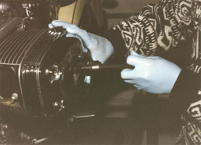 |
Pulling off the plug cap. |
After the sparkplug cap has been removed, shine a flashlight down the sparkplug tunnel. If you see any dirt, rocks or crap, now is the time to get it out of there. If you have compressed air available, (consider eye protection here) use this to blow the crap out. Blowing the crap out will see you pointing the air nozzle down the sparkplug tunnel and letting her rip! In addition to blowing down the tunnel, also blow down the fins of the head. These little cooling openings are how all that crap gets in there.
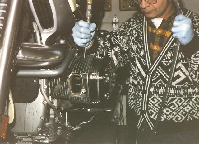 |
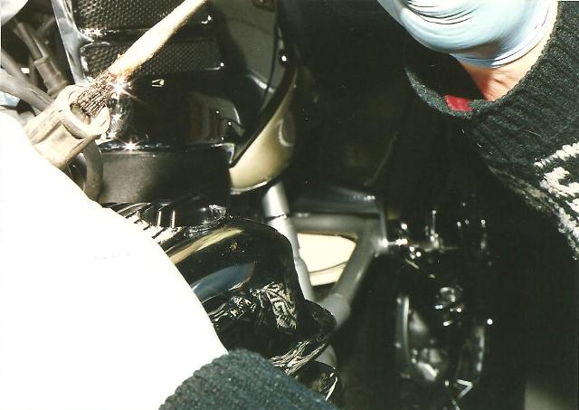
Blowing out all the road dirt. You don't have to remove the exhaust to do this job, I just happen to have them off while doing this artical. |
Removing the sparkplugs requires no special tools. Although BMW has a special tool #12 3 510, all you really need is a 15mm deep socket (the one pictured below is a Snap-On) coupled with a 6” extension and you are there. The nice thing about the BMW tool, it has a built in magnetic ring to retain the plug.
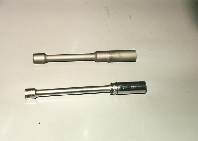 |
The BMW tool on top, a deep socket and extension on the bottom. |
Ok, now we have the trim covers off, plug caps off and the sparkplugs out, let’s get the rocker covers off.
Place a drip pan under each rocker cover, (I use old bread tins from garage sales) as there will be some oil drips. Using a T40 Torx, (I like to use a T40 Torx drive socket on a 3/8 speed wrench for this job) undo the 4 bolts holding on each rocker cover. It’s not necessary to remove the bolts from the rocker covers, just make sure they have cleared the threads in the head.
If your rocker covers have never been off before, it’s not uncommon for them to be stuck even with all the bolts undone. Simply “rap” the front and rear edges with a soft-faced hammer until they free up. What ever you do, don’t try to pry the covers off with a screwdriver, as damage will result.
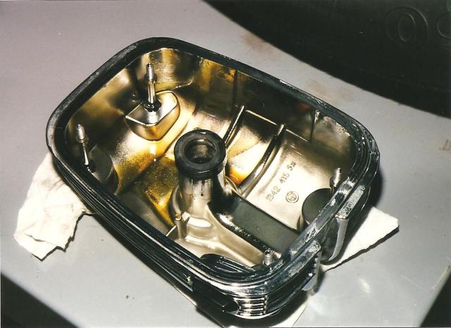 |
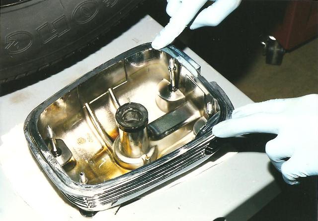
Set the rocker covers out-side (or shiny side) down on a soft, clean rag. |
Lift away the rocker covers and set out-side down on a nice clean rag, (beside their prospective heads). Setting the covers out-side down on a clean rag will reduce any chances of unintentional damage. Often when rocker covers are removed, the rubber ring around the sparkplug tunnel stays behind on the head. Before you give yourself the chance to forget it, remove the rubber ring from the head and slip it back on the rocker cover. The rubber gasket around the perimeter of the rocker cover stays on the head. The only other piece that may be dislodged whilst removing the rocker covers is the little rubber bumper that resides on the lower front knob just below the rocker arm stud. Be sure when refitting the rubber bumper, the ramp or tapered portion faces forward.
 |
Check to be sure the rubber bumper is back on properly. |
The following is subject to interpretation, this is the way I do the adjustment and am quite pleased with the outcome. After studying the way BMW suggests to carry out this procedure, along with some experimentation, this is the method I have settled on.
I usually have the bike on the BMW service center stand while performing a valve adjustment, so the rear wheel is free to turn. I will also shift the transmission up into 5th gear and rotate the engine with the back wheel. If your rear wheel isn’t elevated, remove the 4 bolts holding on the front plastic engine cover and horn (the horns plug has a little lock on the top of it that you will have to depress to unplug it). The engine may now be rotated using the front crank bolt, (only turn in a clockwise fashion to avoid unintentional loosening).
In order to be able to adjust the valves, TDC or Top Dead Center on the head you are working on must be found. I always start valve adjustment on the left head, so we’ll start there. To find TDC on this first head, rotate the engine until the intake rockers, (rockers to the rear) move in then back out. As soon as the intake rockers come out, this indicates that the engine is approaching compression stroke, (when all the valves on this head are closed). Shine a flashlight beam down the sparkplug tunnel, the black mottled crown of the piston should be in sight. Slowly rotate the engine until the piston crown is as high as possible, the engine is now on TDC.
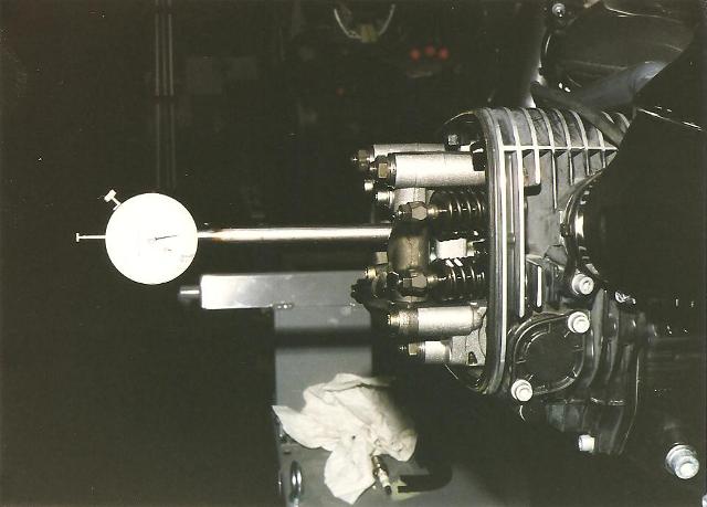 |
The tool I made to indicate top dead center. |
Yes, you can pull out the little plastic plug on the other side of the engine and look for the “OT” marks on the flywheel, but getting that darned plug back in is a real pain. I’ve gone through the trouble of making a special tool with an indicator to show TDC but it’s really not necessary. Sighting the piston through the sparkplug hole is plenty good enough.
Now that the engine is on TDC, (on this side anyway) let’s continue on with valve adjustment. Again, this way works for me as well as those I’ve trained.
Tools needed for adjustment:
| 1 | 10mm box end wrench |
| 1 | 3mm hex key |
| 2 | .15mm thickness gages (feeler gages) .006” |
| 2 | .30mm thickness gages (feeler gages) .012” |
Wurth, the fastener people, supplies the brand of thickness or feeler gage I use.
The idea here is to adjust both intake rockers together then both exhaust rockers. Adjusting both rockers at the same time insures a more accurate, and in time, quicker adjustment.
 |
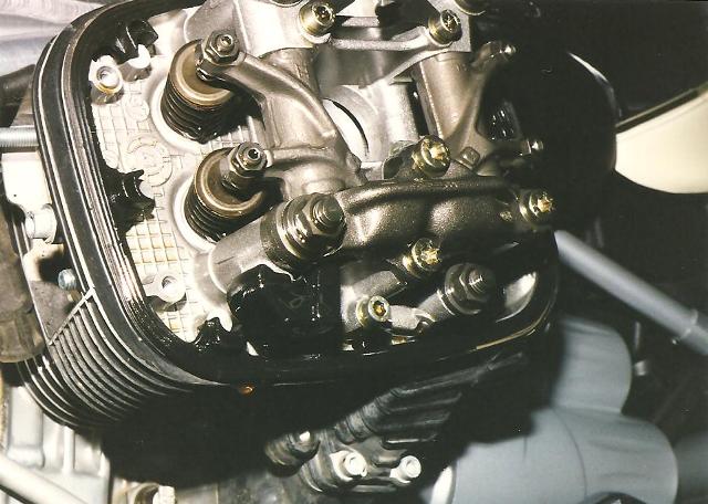
Adjusting the intake valves. |
Starting with the intake, lift the rockers (one at a time) with your fingers and try to poke in the .15mm gage, (the gage fits between the adjuster bucket and the top of the valve stem). If the gage won’t go in, slacken both the lock nut and the adjuster until the gage slips in. Do the same with the second adjuster, both gages need to be in place to continue. I will often leave the lock nuts loose until both feeler gages are adjusted a little tight. Snugging down the lock nuts will loosen the feeler gages. The correct finished adjustment will find both feeler gages may be slid back and forth with the same tension. The gage must not be so loose that it will fall out. On the other hand, it must not be so tight that it bends and deforms before allowing it to slide back and forth. Somewhere in between these two extremes is the correct adjustment; the gage should slide back and forth with drag. Recheck that both lock nuts are nice and snug, and then recheck how the feeler gages feel. Intake adjustment is now done.
Repeat this adjustment process with the exhaust valves, (without rotating the engine) except using the .30mm gages. Don’t be surprised or disappointed if it takes a few tries to get things just right.
 |
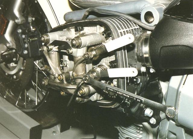
Adjusting the exhaust valves. |
When you feel all is adjusted correctly, move all the adjustment tools to the other side of the motor. Rotate the engine again to find TDC as it will be different from the first side. Proceed with valve adjustment.
Before refitting your rocker covers, dip the tip of your finger into the puddle of oil in the bottom of the rocker cover and put a smear all around the sealing face. This will not only help the rocker cover seal, it will make it easier to remove the next time. Don’t forget to also lube the rubber ring around the sparkplug tunnel.
 |
Smearing a film of oil on the sealing surface of the rocker cover. |
Before offering the rocker cover up to the head, press all the mounting bolts in. With the threaded ends of the bolts extending beyond the sealing edge of the rocker cover, it’s easier to line them up with their respective holes. Start each of the bolts with your fingers before pressing the rocker cover home. With practice, you will get quite good at this. Using a cross pattern, thread the bolts in, pulling down the cover evenly. Continuing to use the cross pattern, snug down all the bolts until they are bottomed out. Once the bolts have bottomed out, it does no good to try to tighten them any more. If you so choose to continue to tighten them more, you risk breaking them off. The tension of the rubber grommets, (under the cover washers) give enough pressure against the bolts to stop them from backing out. When you tighten down the cover bolts and feel little or no resistance against the grommets, it’s time to fit new ones.
Using a small acid brush, brush on a bit of anti-seize onto the threads of your sparkplugs, (in a pinch, graphite from pencil lead will do). Thread the plugs back in and snug them down. Before slipping the sparkplug cap into place, smear a bit of grease or Vasoline around the caps where they contact the plug bodies. This makes it a little easier to remove the caps next time. Slip the caps onto the plugs and press them home. Finish off with replacing the plastic trims over the sparkplug caps.
 |
Greasing the plug cap. |
That’s another job well done!
Copyright © 2012 Pokie Parmidge